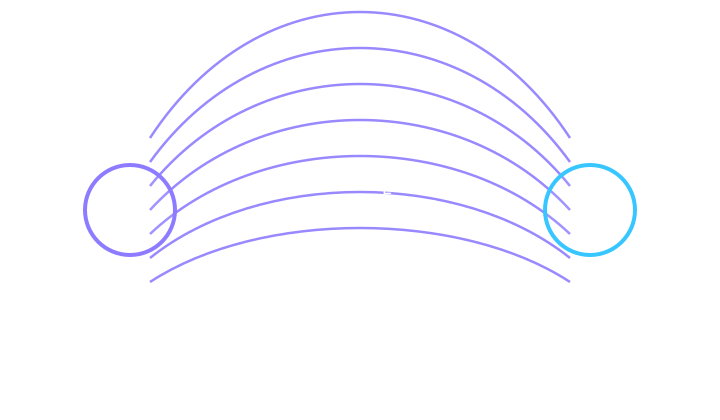
Build electric fields one idea at a time.
Start with the foundations, then explore advanced ideas and calculus at the depth your course needs.
8 of 8 lessons
Electric Field Strength & Force
Define the field with a positive test charge and predict the force on any charge.
Electric Field Lines & Direction
Read direction from a tangent and strength from relative line density.
Point-Charge Fields
Connect source charge, radial direction, and inverse-square distance dependence.
Field Superposition & Null Points
Add signed components and locate where the net field vanishes.
Uniform Fields & Parallel Plates
Link voltage, plate separation, force, acceleration, and particle paths.
Conductors, Shielding & Field Mapping
Test electrostatic equilibrium, curvature, shielding, and safe field maps.
Field Calculus
Integrate ring and line charges and test the point-charge limit.
Gauss’s Law
Use flux and symmetry for spheres, lines, and sheets.
Change one variable. Watch the physics respond.
Explore E = kQ/r², then take the idea into the full lessons.
Map a point-charge field
Field strength is signed by source charge and falls with distance squared.
Everything around the chapter, in one place.
Keep building with practice, classroom presentations, formulae, and a game that puts these ideas to work.
Exam practice
Questions, guided reasoning, and exam-style problem solving.
Browse exam questions →Formula toolkit
Keep the key relationships and their units close to hand.
Review formulae →Members · Classroom presentationClassroom slides
Reveal lesson ideas, examples, and checks in full-screen classroom mode.
Open slides →Lesson files
Find downloadable teaching resources and worksheets in the library.
View files →Field Runner
E = V/d. Set plate voltage and gap to land a charged particle in the target slot.
Play the free chapter game →See it. Read it. Work it.
Connect diagrams to physical relationships and exam reasoning.
Explore diagrams →Guided support
Ask for a hint, check your reasoning, or explore a similar problem.
Ask GioAI →Key ideas to remember
Sources create the field. The field exists before a test charge is placed there. A charge then experiences F⃗ = qE⃗, with a reversal of direction when q is negative.
Visual reference & diagrams
Exam diagrams for this topic2 figures to inspect and practiseQuestions, hints and marking points in one compact subsection.
See it. Read it. Work it.
These figures come from GioPhysics practice papers. Open one, decode the drawing, work the guided questions, then follow its link to the full paper question.
- 01
InspectRead the figure comment.
- 02
TraceFollow labels, arrows and axes.
- 03
AnswerWork one part at a time.
- 04
CheckReveal hints and marking points.
IB
01Figure 4Electric and magnetic fieldsIB
Figure comment
Figure 4A long straight wire is drawn vertically and labelled 'long straight wire'. An arrow drawn along the wire and labelled I gives the direction of the current in it. To the right of the wire, at the same height, a small rectangle labelled 'magnetic field probe' has its near face towards the wire, and a dimension line running perpendicular from the wire to that face is labelled r. A dashed outline of the probe, drawn further to the right at the same height, carries the note 'probe moved to other values of r'.
Read the comment once, then trace every arrow, label, axis or component in the drawing before opening the questions.
Guided questions 5 parts
Reading cue. r is drawn from the wire to the near face of the probe, not to the sensor inside it, and the field being measured points perpendicular to the page, not along the line r.
aState State how the direction of the magnetic field at the probe is related to the plane of the drawing, and state whether the field points the same way once the probe is moved to the dashed position.
Check answer 3 marks
- Right-hand grip rule applied to the current arrow drawn on the wire
- Field at the probe is perpendicular to the plane of the drawing, not along the dimension line r
- Field at the dashed position points the same way, because that position lies on the same side of the wire; only the magnitude falls
bCalculate The wire carries a steady current of 4.0 A. The dimension r is 25 mm for the probe drawn in full and 100 mm for the dashed position. Calculate the magnetic flux density at each of these two positions.
Check answer 3 marks
- Use of B = μ₀I/(2πr), with r the perpendicular distance drawn from the wire
- At r = 0.025 m: B = (2 × 10⁻⁷ × 4.0)/0.025 = 3.2 × 10⁻⁵ T (32 μT)
- At r = 0.100 m: B = (2 × 10⁻⁷ × 4.0)/0.100 = 8.0 × 10⁻⁶ T (8.0 μT)
cDetermine The dimension r is drawn to the near face of the probe, but the sensing element sits 5.0 mm behind that face. Determine the percentage by which each recorded flux density falls below μ₀I/(2πr) when r is recorded as 25 mm and when it is recorded as 100 mm, and state which end of a graph of B against 1/r is distorted more.
Check answer 4 marks
- True separation is r + 5.0 mm, so the recorded value is in the ratio r/(r + 5.0 mm) of the expected one
- At r = 25 mm: 25/30, so the reading is 17% below the expected value
- At r = 100 mm: 100/105, so the reading is 4.8% below the expected value
- Readings taken closest to the wire are affected most, so the graph bends below a straight line at the large-1/r end
dDiscuss The wire is drawn extending well above and well below the level of the probe. Discuss what happens to the readings at both probe positions if the wire is shortened until its ends lie only a few centimetres above and below that level.
Check answer 4 marks
- μ₀I/(2πr) assumes an infinitely long wire, so that current elements at all distances along it contribute
- A shortened wire is missing those contributions, so every measured value of B is smaller than μ₀I/(2πr)
- The shortfall grows with r, since the shortened wire subtends a smaller angle at the probe, so the dashed far position is affected more than the near one
- The plotted line therefore falls away from a straight line at the small-1/r end, and its gradient no longer gives the true current
Transfer challenge
Two long straight parallel wires are 60 mm apart and each carries a steady current of 4.0 A, but in opposite directions. Determine the magnitude of the magnetic flux density at the point midway between them, and state the direction of the field there relative to the plane containing the two wires.
Check answer 4 marks
- Each wire is 30 mm from the midpoint, so each contributes B = 2 × 10⁻⁷ × 4.0/0.030 = 2.7 × 10⁻⁵ T
- Because the currents are opposite, the two contributions at the midpoint act in the same direction and add
- Total B = 5.3 × 10⁻⁵ T
- Field there is perpendicular to the plane containing the two wires
02Figure 5Electric and magnetic fields · Motion in electromagnetic fieldsIB
Figure comment
Figure 5Side view of the arrangement. At the left a cathode plate marked − faces an anode plate marked + which has a small hole in it at the level of the beam; below, the two plates are joined by wires through a cell labelled 500 V, whose positive terminal is connected to the anode. Arrows show an electron leaving the cathode, passing through the hole in the anode and travelling on to the right, where it crosses into a large rectangular region drawn with a dashed boundary and filled with crosses, labelled 'uniform magnetic field, B = 2.5 mT, into the page'. Inside that region the electron's path is drawn as an arc that curves steadily downwards away from its original straight line.
Read the comment once, then trace every arrow, label, axis or component in the drawing before opening the questions.
Guided questions 5 parts
Reading cue. The crosses mean the field is into the page and the drawn arc bends downwards; the charge is negative, so check your rule reproduces that downward force before trusting any later step.
aState State the direction of the magnetic force on the electron at the instant it crosses the dashed boundary, and state the direction of the conventional current that the moving electron represents.
Check answer 2 marks
- Conventional current is directed to the left, opposite to the drawn motion of the electron
- Force is directed downwards, towards the bottom of the page, in agreement with the way the drawn arc bends
bDetermine Determine the time the electron would take to complete one full circle inside the field region, and state how that time would differ if the electron had been accelerated through 2000 V instead of 500 V.
Check answer 4 marks
- Use of T = 2πm/(qB)
- T = 2π × 9.11 × 10⁻³¹/(1.60 × 10⁻¹⁹ × 2.5 × 10⁻³)
- T = 1.4 × 10⁻⁸ s
- Time would be unchanged, because the period does not depend on the speed
cDetermine The dashed region is 5.0 cm wide in the direction of the electron's initial motion, and is tall enough that the electron never reaches its upper or lower edge. Determine the greatest distance the electron penetrates into the region, and determine where it leaves.
Show a hint
The centre of the circular path lies on the perpendicular to the velocity drawn at the entry point.
Check answer 4 marks
- Speed on entry v = √(2eV/m) = 1.3 × 10⁷ m s⁻¹
- Radius r = mv/(eB) = 1.21 × 10⁻²³/(4.0 × 10⁻²²) = 3.0 × 10⁻² m
- Greatest penetration equals r, i.e. 3.0 cm after a quarter circle, which is less than the 5.0 cm width
- Electron turns through 180° and leaves through the boundary it entered, 2r = 6.0 cm below the entry point
dEvaluate The accelerating potential difference is raised from 500 V to 1000 V with everything else unchanged. Evaluate whether the electron can be made to leave through the far edge of the region drawn, either by this change or by raising the accelerating potential difference further.
Check answer 4 marks
- r ∝ √V, so the radius rises by a factor of √2, from 3.0 cm to 4.3 cm
- Penetration still equals r, and 4.3 cm is less than the 5.0 cm width, so the electron still turns back
- Penetration reaches 5.0 cm when r = 5.0 cm, requiring V = 500 × (5.0/3.0)² ≈ 1.4 × 10³ V
- Above about 1.4 kV the electron does reach the far edge, so the behaviour drawn is a consequence of this particular accelerating voltage rather than a general feature of the arrangement
Transfer challenge
In a cyclotron, protons travel in a uniform magnetic field of 0.85 T and are accelerated each time they cross the gap between the two dees. Determine the frequency at which the accelerating potential difference must alternate, and state why this frequency need not be changed as the protons speed up. The mass of a proton is 1.67 × 10⁻²⁷ kg.
Check answer 4 marks
- Recognition that the supply frequency must equal the orbital frequency, f = qB/(2πm)
- f = (1.60 × 10⁻¹⁹ × 0.85)/(2π × 1.67 × 10⁻²⁷)
- f = 1.3 × 10⁷ Hz (13 MHz)
- Frequency is fixed because the orbital period does not depend on speed; the radius grows but the time per revolution does not
Move without losing your place.
Extra challenging questions
Take the ideas further with course-specific extension questions, supplied-data graphs and worked solutions.