Chapter 22 · Circuits · Lesson 13.1
Circuit Symbols & Diagrams
A shared language for circuits
Engineers and scientists record circuits with standard symbols so any complex arrangement can be drawn — and read — clearly and precisely by anyone.
Read the relationship. Check its limits.
Lesson Overview
A circuit diagram uses standard symbols and straight lines to show how components are connected into loops.
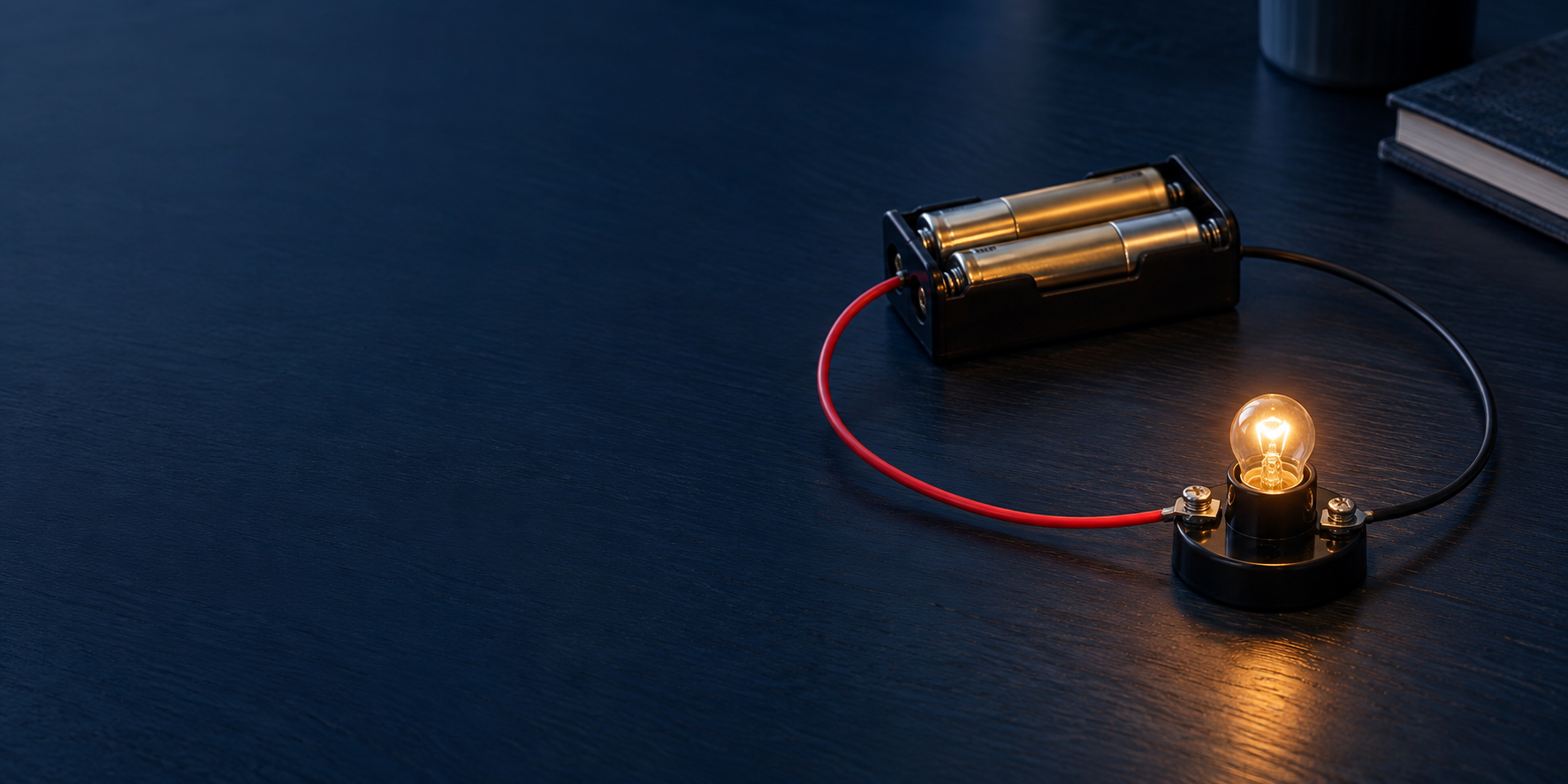
A cell, a switch, and a lamp drawn in one rectangle of lines means: close the switch and charge can flow around one complete loop, lighting the lamp.
Learning Objectives
- Recognise standard component symbols
- Trace connections and complete loops
- Place ammeters and voltmeters correctly
- Distinguish a junction from a crossing
Common Circuit Symbols
Select a symbol to read its meaning.
Cell. One electrochemical cell. The longer line is the positive terminal.
Symbols vary slightly between conventions. Use the version specified by your course; the component’s function and connections remain the same.
Interactive Circuit Builder
Change one input. Compare the graph and its readout before drawing a conclusion.
Equivalent load resistance12 Ω
Supply current0 A
Voltage across load 10 V
Load 1 · current / power0 A / 0 W
Guided builder: add up to four loads, then choose a series chain or parallel branches. Readings update immediately. With the switch open, the voltage across a connected load is 0 V; the supply voltage is across the switch. Lamps use fixed resistance here, so their colour indicates current, not a calibrated brightness. Use this on-screen model only; real circuit ratings and hazards are not simulated.
Guided ideal DC circuits with zero-resistance wires, an ideal supply and meters. Lamps are modelled as fixed resistances; a real filament warms up and changes resistance. Never test meter-placement faults on a real supply.
Key Formulae
- Complete loop
- supply → components → supplyCharge can only flow when there is an unbroken path from one terminal of the supply, through the components, and back to the other terminal.Current needs an unbroken conducting path
- Ammeter placement
- in seriesAn ammeter counts the charge flowing through a point, so it sits in the path of the current — in series with the component.An ideal ammeter has zero resistance
- Voltmeter placement
- in parallelA voltmeter compares the energy per charge between two points, so it connects across a component — in parallel with it.An ideal voltmeter has infinite resistance
Use the units shown by each control. Convert millimetres to metres for wire calculations and minutes to seconds for energy.
Key Concepts
Practice Questions
Build the physical model.
A circuit diagram is a map, not a picture. Each standard symbol stands for a component; straight lines stand for connecting wire assumed to have no resistance. A circuit only works when the loop from one terminal of the supply to the other is complete.
Sources
A cell is one unit; a battery is two or more cells. The longer line marks the positive terminal. A power supply symbol stands for mains-driven sources.
Control and protection
Switches break the loop; fuses melt to break it automatically when current is too large; variable resistors adjust current smoothly.
Measurement and output
Ammeters read current in series, voltmeters read potential difference in parallel, and lamps, motors, buzzers, and resistors transfer energy out of the circuit.
Sensing and one-way components
A thermistor is a resistor rectangle with a diagonal bar across it. The kind used at this level is NTC: its resistance falls sharply as it gets hotter. A light-dependent resistor is the same rectangle with two arrows pointing in at it, and its resistance falls as the light on it grows brighter. Both are input components — they turn a temperature or a light level into a resistance the rest of the loop can respond to. A diode is a triangle pointing into a bar: it passes conventional current only in the direction the triangle points, and blocks it the other way, which is what makes it useful for turning alternating current into direct. A light-emitting diode is the same symbol with two arrows pointing away from it.
Know what the model can tell you.
Assumptions & boundaries
Guided ideal DC circuits with zero-resistance wires, an ideal supply and meters. Lamps are modelled as fixed resistances; a real filament warms up and changes resistance. Never test meter-placement faults on a real supply.
The lines in a diagram are not drawn to scale and their length does not matter. Connecting wire is treated as resistance-free, so only the components and how the loops connect them change the physics.
How must an ammeter and a voltmeter be connected to measure a lamp's current and potential difference?
Choose an answer to test the idea.
Worked Examples
State the assumptions, convert units, calculate and check the physical meaning. Check which ideal-circuit assumptions apply.
EasyName the two meters in a test circuit and how each must be connected to a lamp.
- The ammeter reads current: in series, in the lamp's loop.
- The voltmeter reads p.d.: in parallel, across the lamp.
Ammeter in series, voltmeter in parallel
MediumDraw a circuit to measure the resistance of a lamp using a cell, a switch, an ammeter, and a voltmeter.
- Draw one loop: cell → switch → ammeter → lamp → back to the cell.
- Connect the voltmeter in parallel across the lamp only.
- Close the switch, read I and V, then use R = V/I.
Series loop of cell, switch, ammeter, and lamp, with the voltmeter across the lamp
HardTwo wiring faults, each made on its own. (a) The ammeter is connected in parallel with the lamp. (b) In a separate attempt, the voltmeter is connected in series in the loop. Predict the meter readings and the lamp in each case, treating the faults separately.
- Fault (a) alone: the ammeter's near-zero resistance short-circuits the lamp, so almost all the current bypasses it. The lamp goes out and the ammeter carries a dangerously large current, limited only by the cell and the leads.
- Fault (b) alone: the voltmeter's near-infinite resistance now sits in the only loop, so the current falls to almost nothing. The lamp stays dark and the voltmeter reads close to the full e.m.f., because nearly all of it is dropped across the voltmeter itself.
- Judge each fault on its own. If both were made at the same time the series voltmeter would still choke the loop, so the parallel ammeter would not draw a large current — the danger in (a) exists only while the rest of the circuit is wired correctly.
(a) lamp out, ammeter passes a dangerously large current; (b) current ≈ 0, lamp dark, voltmeter reads ≈ the e.m.f.
ChallengingDesign a circuit to measure a lamp's resistance at three different brightnesses using one cell, one variable resistor, an ammeter, and a voltmeter. Explain each component's role.
- Series loop: cell → variable resistor → ammeter → lamp → cell; voltmeter across the lamp only.
- The variable resistor sets the loop current, giving three operating points; the meters record (I, V) pairs at each.
- R = V/I at each point — expect R to rise with brightness as the filament heats.
Rheostat in series to set current; R = V/I from each (I, V) pair, rising as the lamp brightens
Interactive circuit graph
Read the topology before the values.
Use this connectivity map alongside 13.1 Circuit Symbols & Diagrams. Change the network, then select a node or branch to see what the graph preserves.
- Nodes
- Points where electrical connections meet.
- Branches
- Lines or general impedances connecting two nodes.
- Simplification
- Component details, such as specific resistor values, are hidden to focus purely on connectivity.
Series loop: 3 nodes and 3 branches. Select a node or branch to investigate it.
Exam diagrams for this topic2 figures to inspect and practiseQuestions, hints and marking points in one compact subsection.
See it. Read it. Work it.
These figures come from GioPhysics practice papers. Open one, decode the drawing, work the guided questions, then follow its link to the full paper question.
- 01
InspectRead the figure comment.
- 02
TraceFollow labels, arrows and axes.
- 03
AnswerWork one part at a time.
- 04
CheckReveal hints and marking points.
IGCSE
01Fig. 3.1Electric circuitsIGCSE
Figure comment
Fig. 3.1A circuit diagram of two resistors connected side by side between the same pair of points. A wire arrives from the left and reaches a junction, marked with a dot, where it divides into two branches. The upper branch contains a resistor labelled 6.0 ohm and the lower branch a resistor labelled 3.0 ohm. The two branches rejoin at a second junction dot on the right, from which a single wire continues away to the right.
Read the comment once, then trace every arrow, label, axis or component in the drawing before opening the questions.
Guided questions 5 parts
Reading cue. Both resistors lie between the same two junction dots, so they have the same p.d. across them; it is the current, not the voltage, that divides at the left-hand dot.
aState State which of the two resistors in Fig. 3.1 carries the larger current, and give a reason.
Check answer 2 marks
- the 3.0 Ω resistor
- both branches lie between the same two junctions and so have the same p.d. across them, and I = V/R, so the smaller resistance carries the larger current
bDetermine The potential difference between the two junction dots in Fig. 3.1 is 12 V. Determine the current in each resistor and the current in the single wire arriving from the left.
Check answer 3 marks
- current in the 6.0 Ω resistor = 12/6.0 = 2.0 A
- current in the 3.0 Ω resistor = 12/3.0 = 4.0 A
- current in the wire from the left = 2.0 + 4.0 = 6.0 A
cDetermine Each resistor in Fig. 3.1 is rated at a maximum power of 12 W. Determine the largest potential difference that may safely be applied between the two junction dots, and the current drawn at that potential difference.
Check answer 4 marks
- for the 3.0 Ω resistor, V = √(PR) = √(12 × 3.0) = 6.0 V
- for the 6.0 Ω resistor, V = √(12 × 6.0) = 8.5 V, so the 3.0 Ω resistor is the one that limits the pair
- largest safe p.d. = 6.0 V
- current drawn = 6.0/6.0 + 6.0/3.0 = 3.0 A
dExplain A student claims that connecting a third resistor between the same two junction dots in Fig. 3.1 must raise the total resistance, because there is then more resistance present. Explain why the student is wrong, and state the largest total resistance the arrangement could ever have once a third resistor is added there.
Check answer 4 marks
- a resistor connected between the same two dots is in parallel with the others and gives the current an extra path
- for the same p.d. the total current is therefore larger, and R = V/I, so the total resistance falls
- the pair alone gives 1/R = 1/6.0 + 1/3.0, so R = 2.0 Ω
- adding a third branch can only bring the total below 2.0 Ω, so 2.0 Ω is a value the arrangement approaches but never reaches
Transfer challenge
Three identical lamps, each of resistance 240 Ω, are connected in parallel across a 240 V supply. Calculate the total current drawn, and state the effect on the other two lamps if one filament breaks.
Check answer 3 marks
- current in each lamp = 240/240 = 1.0 A
- total current = 3 × 1.0 = 3.0 A
- the other two lamps still have the full 240 V across them and are unaffected, and the total current falls to 2.0 A
02Fig. 7.1Electrical quantities · Electric circuitsIGCSE
Figure comment
Fig. 7.1Circuit diagram. From the positive terminal of the 12 V battery, drawn at the foot of the circuit with its long plate on the left, the wire runs round to a resistor labelled 40 ohm. Beyond that resistor the circuit reaches a junction and divides into two parallel branches, the upper one containing a resistor labelled 30 ohm and the lower one a resistor labelled 60 ohm. The branches rejoin at a second junction, and a single wire returns from there to the negative terminal of the battery.
Read the comment once, then trace every arrow, label, axis or component in the drawing before opening the questions.
Guided questions 5 parts
Reading cue. The 40 Ω sits before the first junction dot, so it carries the whole battery current; only past that dot is the current shared between the 30 Ω and the 60 Ω.
aDetermine The current drawn from the battery in Fig. 7.1 is 0.20 A. Determine the potential difference across the 40 Ω resistor.
Check answer 2 marks
- the 40 Ω resistor lies before the junction, so it carries the whole 0.20 A
- V = IR = 0.20 × 40 = 8.0 V
bDetermine Determine the power dissipated in the 40 Ω resistor in Fig. 7.1, and the total power supplied by the battery.
Check answer 2 marks
- power in the 40 Ω resistor = I²R = 0.20² × 40 = 1.6 W
- total power from the battery = VI = 12 × 0.20 = 2.4 W
cDetermine The 40 Ω resistor in Fig. 7.1 is replaced by a variable resistor. Determine the resistance it must be set to for the potential difference across the parallel pair to be 6.0 V.
Check answer 3 marks
- the parallel pair has a combined resistance of (30 × 60)/90 = 20 Ω, so the current is 6.0/20 = 0.30 A
- p.d. across the variable resistor = 12 − 6.0 = 6.0 V
- R = V/I = 6.0/0.30 = 20 Ω
dExplain The 30 Ω resistor in Fig. 7.1 is replaced by a filament lamp whose resistance rises as it warms up. Explain what happens to the potential difference across the 40 Ω resistor as the lamp warms, and state whether the current in the 60 Ω resistor rises or falls.
Check answer 4 marks
- the resistance of the lamp rises, so the combined resistance of the parallel pair rises
- the total resistance of the circuit rises, so the current drawn from the battery falls
- the p.d. across the 40 Ω resistor is that current × 40, so it falls
- the parallel pair therefore takes a larger share of the 12 V, so the current in the 60 Ω resistor, equal to that p.d. divided by 60, rises
Transfer challenge
A 9.0 V battery is connected to a 200 Ω resistor in series with a thermistor whose resistance is 400 Ω at room temperature. Calculate the potential difference across the 200 Ω resistor, and state how it changes when the thermistor is warmed.
Check answer 3 marks
- total resistance = 200 + 400 = 600 Ω, so I = 9.0/600 = 0.015 A
- p.d. across the 200 Ω resistor = 0.015 × 200 = 3.0 V
- warming lowers the resistance of the thermistor, so the current rises and the p.d. across the 200 Ω resistor rises
Put the ideas to work.
From diagrams to circuits
Trace the path from each supply terminal before assembling a low-voltage circuit.
Reading a schematic
Component symbols describe function and connectivity, not physical size or position.
Before you move on.
- Recognise standard component symbols.
- Trace connections and complete loops.
- Place ammeters and voltmeters correctly.
Quick Quiz
Five questions. Answers stay in this open page only.
Downloads & Resources
Try a Game
Circuit RushConnect the components and put circuit reasoning into practice.
Play now →